
Request A Quote

Phone: 416-244-6476
Email:

    2026 Best Mount Motor Types for Global Buyers

    A Mount Motor is more than a component selected by frame size. Its mounting arrangement affects alignment, vibration, service access, and how reliably a drive fits the machine. The U.S. Department of Energy’s Improving Motor and Drive System Performance: A Sourcebook for Industry estimates that motor-driven systems account for roughly 60–70% of electricity use in U.S. manufacturing. That figure makes efficiency and correct specification practical purchasing concerns, not minor details. But energy use alone cannot identify the right motor.

    For global buyers, the useful comparison starts with the installation. Foot-mounted motors suit many base-supported machines; flange and face mounts can save space or simplify direct coupling. IEC 60034-7 provides standardized designations for motor mounting arrangements, helping buyers compare configurations across suppliers. Check the actual duty cycle, shaft dimensions, enclosure, cooling method, voltage, frequency, and local service support before comparing quotations. Small differences matter. A pump in a humid plant and a conveyor exposed to dust may need different protection, even when their power ratings match.

    Still, a neat table can mislead. Catalog labels do not guarantee identical dimensions or operating performance, and regional availability can change lead times. Ask suppliers for drawings, test documentation, and clear confirmation of the specified mounting code. This guide reviews common Mount Motor types and the trade-offs buyers should weigh. The “best” choice depends on the machine, operating conditions, and maintenance plan—not just the lowest purchase price.
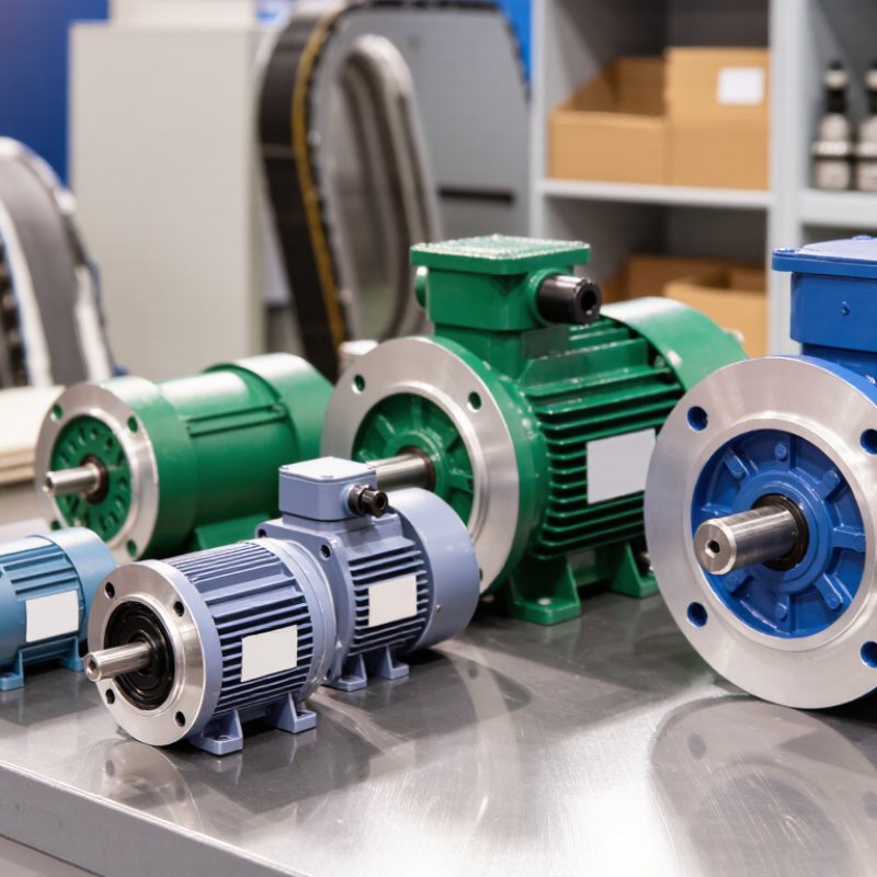
    2026 Best Mount Motor Types for Global Buyers

    What Mount Motor Types Are and How They Are Classified

    Mount motor types describe how a motor attaches to a machine, not how it produces power. Common arrangements include foot-mounted, flange-mounted, and face-mounted designs. A foot-mounted motor rests on a base, with bolts securing its feet to a level surface. A flange-mounted motor connects through a circular flange, often directly to a gearbox or machine housing. Face-mounted designs use a front mounting face and may suit compact assemblies. Fit matters most.

    Some motors combine mounting features, such as feet and a flange. Buyers may also see designations that specify shaft orientation or installation position. These details affect clearance, alignment, and how loads transfer into the frame. The labels can mislead. Two motors with similar names may have different bolt patterns or shaft dimensions, so check the manufacturer’s dimensional drawing before ordering.

    Mounting type is separate from motor technology. An induction motor, servo motor, or DC motor can each be offered with particular mounting arrangements, depending on the product. Confirm the frame size, shaft diameter, bolt spacing, mounting position, and required torque. Measure twice. For example, a flange that fits the housing but leaves too little room for wiring can delay installation. Field conditions matter, and drawings do not always show every obstruction.

    Common Motor Mounts: Foot, Flange, Face, and Combined Designs

    Foot-mounted motors rest on a level base, with feet bolted to a frame or machine bed. They suit many horizontal installations, but soft feet or uneven shims can twist the housing and disturb alignment. Check shaft height, bolt spacing, and available clearance before ordering. Small errors matter.

    Flange-mounted motors attach through a machined flange, which helps support direct coupling where floor space is limited. Face-mounted designs use front-face holes or a pilot register; the exact pattern varies by motor and equipment. Combined foot-and-flange designs offer more installation options, but unused mounting points do not guarantee interchangeability. Fit is not universal. IEC 60034-7 classifies construction and mounting arrangements under the IM code, making that code useful for comparing drawings—not a substitute for checking dimensions.

    The International Energy Agency’s report Energy-Efficiency Policy Opportunities for Electric Motor-Driven Systems estimates that motor-driven systems consume about 45% of global electricity. That scale makes installation quality worth attention: vibration, misalignment, and poor access can complicate maintenance.

    A common oversight is checking only the bolt pattern. Also verify flange pilot diameter, shaft extension, terminal-box position, load direction, and lifting access. A tidy drawing can still hide a cramped wrench path. Confirm the full assembly dimensions with the equipment supplier before committing to a mount.

    How Mounting Style Affects Installation, Load, and Performance

    2026 Best Mount Motor Types for Global Buyers

    How Mounting Style Affects Installation, Load, and Performance

    A motor’s mounting style is more than a fit issue. It determines how loads reach the frame, how technicians align the shaft, and how easily the unit can be serviced. Foot-mounted motors sit on a base and suit many horizontal drives. Flange-mounted types attach directly to a machine, saving floor space but demanding accurate face alignment. Small errors matter.

    IEC 60034-7 defines motor mounting arrangements, including shaft orientation and mounting configuration. Use its designations when comparing supplier drawings across markets. For vertical installations, confirm whether the motor and bearings are designed for the actual thrust load. A horizontal motor turned upright may look compatible, yet bearing lubrication and load paths can differ. Check the manual.

    The U.S. Department of Energy’s 1998 Industrial Electric Motor Systems Market Opportunities Assessment estimated that motor systems used about 69% of manufacturing electricity. That figure is dated and does not measure mounting effects. Still, it shows why installation choices deserve attention. A poor base can introduce vibration, loosen fasteners, and shorten bearing life. Field experience is not always tidy: even a carefully specified motor can underperform when the driven equipment’s weight, coupling, or service access was overlooked. Check mounting dimensions, allowable loads, cooling clearance, and alignment tolerances before ordering.

    Comparing Motor Types for Different Applications and Environments

    AC induction motors suit pumps, fans, and conveyors that run steadily for long periods. Their simple construction handles routine industrial duty, but speed control may require additional drive equipment. Brushed DC motors offer straightforward speed adjustment and strong starting torque in compact machinery. Brush wear, however, adds maintenance. Brushless DC motors reduce that wear and work well in positioning equipment or battery-powered systems. Stepper motors can hold defined positions at low speeds, though missed steps are possible when loads exceed their limits. Servo motors provide precise feedback control, but their tuning and wiring take more care. No single type fits every task.

    The environment can change the decision. In a dusty workshop, sealed housings and protected connectors matter as much as motor technology. Near washdown areas, check the motor’s ingress protection rating and compatible cleaning conditions; do not assume a sealed-looking case is waterproof. Outdoor installations need attention to moisture, temperature swings, and corrosion. A cold start can expose weaknesses that a warm test bench never shows. Mounting also matters: foot, flange, or face-mounted designs must match the frame and load alignment. Vibration, shaft coupling, and available service space deserve inspection before purchase. A neat specification sheet can still miss these details.

    2026 Best Mount Motor Types for Global Buyers - Comparing Motor Types for Different Applications and Environments

    Mounting type Typical configuration Common applications Main advantages Selection and environment considerations
    Foot-mounted (IM B3) Motor feet are bolted to a base or frame; shaft is generally horizontal. Pumps, fans, compressors, conveyors, and general-purpose machinery. Straightforward installation and alignment; widely used where a stable base is available. Check base rigidity, bolt pattern, shaft alignment, and vibration. Protect the motor appropriately where dust, moisture, or washdown is present.
    Flange-mounted (IM B5) A large flange attaches the motor to a machine or housing; mounting is typically at the drive end. Pumps, gearboxes, process equipment, and machines with a matching flange interface. Compact drive arrangement that can simplify connection to equipment without a separate motor base. Confirm flange dimensions, pilot fit, shaft dimensions, and supported loads. The driven machine must provide a sufficiently rigid mounting surface.
    Face-mounted (IM B14) A smaller face flange attaches to the machine, commonly using threaded mounting holes. Compact gear drives, small pumps, packaging machinery, and equipment with limited mounting space. Space-saving interface suited to compact machinery and smaller drive assemblies. Verify the face pattern, thread size, pilot, and permissible loads. Do not assume a face mount is interchangeable with a large-flange mount.
    Foot-and-flange-mounted (IM B35) Motor includes feet and a large flange; the installation uses the mounting arrangement specified by the machine design. Applications requiring installation flexibility, including pumps, fans, and industrial machinery. Offers both foot and flange mounting features, which can accommodate different equipment layouts. Use only the intended mounting points and confirm that the support carries the motor and driven-machine loads. Check alignment and avoid stressing the housing.
    Foot-and-face-mounted (IM B34) Motor includes feet and a smaller face flange for mounting to compatible equipment. Compact gear units, small process equipment, and installations that may use a base or face interface. Combines foot mounting with a compact face interface, providing layout options for compatible designs. Confirm that the machine interface matches the face pattern and that the selected mounting method is supported by the motor documentation.
    Vertical mounting (for example, IM V1) Motor is installed with a vertical shaft; the exact arrangement depends on shaft direction and mounting interface. Vertical pumps, mixers, and machinery designed around a vertical drive shaft. Fits equipment where a vertical shaft orientation is required and can reduce the need for additional drive-layout changes. Check the exact mounting code, shaft orientation, bearing arrangement, axial load capacity, and drainage or moisture exposure. Not every horizontal motor is suitable for vertical operation.
    Special-purpose mounting Custom brackets, rails, frames, or equipment-specific interfaces. Mobile equipment, retrofits, confined spaces, and machinery with non-standard interfaces. Can address unusual space, access, or equipment-integration requirements. Have the support structure and fasteners checked for load, vibration, alignment, and operating conditions. Confirm the arrangement with the motor and driven-equipment documentation.

    Selection note: IEC mounting designations describe mounting arrangements; verify the applicable standard, dimensions, shaft orientation, load limits, enclosure protection, and operating conditions before ordering. The most suitable mount depends on the driven equipment and installation environment.

    How Global Buyers Can Check Standards and Select a Compatible Mounting Type

    2026 Best Mount Motor Types for Global Buyers

    Before choosing a motor, match its mounting arrangement to the machine and installation space. Common options include foot mounting, flange mounting, and face mounting. IEC 60034-7 defines mounting arrangements and their IM codes. Treat the code as a useful reference, not a complete fit guarantee. Check the motor’s dimensional drawing against the equipment drawing.

    Measure the mounting holes, shaft height, flange diameter, and shaft extension. Confirm the required orientation and whether the motor must support a particular load direction. Small differences matter. A few millimeters can prevent a clean installation or force changes to a coupling. Ask the supplier to confirm dimensions in writing, especially when replacing an older motor.

    Check the applicable electrical and safety standards for the destination and installation, then compare the motor nameplate and technical documents. Also verify voltage, frequency, enclosure rating, and operating conditions. A familiar mounting code may still describe a different shaft or flange detail. It is easy to assume two motors are interchangeable; that assumption deserves a second check. When drawings are incomplete, request clarification before ordering.

    Article Source: