
How to Choose the Right Chamfering Cutter for Your Needs?
Choosing the right Chamfering Cutter is a small decision with visible consequences. A sharp edge can remove burrs cleanly. A poor match can leave chatter marks, uneven widths, or a damaged workpiece.
Industry data shows why this choice matters. Grand View Research estimated the global cutting tools market at about USD 23.85 billion in 2023. MarketsandMarkets projected continued growth through 2029. These reports measure broad cutting tools, not chamfering products alone. Their estimates also differ. That difference deserves attention.
Dr. Tony L. Schmitz, a recognized machining researcher, offers a useful principle: “Tool selection must match the process, not just the material.” This statement is presented as a practical paraphrase of his process-planning guidance, rather than a verified verbatim quotation. In real workshops, the decision includes more than carbide versus high-speed steel. Consider the chamfer angle, cutter diameter, spindle speed, feed rate, tool reach, and machine rigidity. A 90-degree cutter may suit a standard edge break. A countersink-style cutter may perform better around a drilled hole. Coating choice also matters when cutting stainless steel, hardened steel, aluminum, or composites.
There is no universal winner. Sometimes the catalog recommendation fails on an older machine. Sometimes a cheaper cutter produces the cleanest result. That is not a rule; it is a reminder to test carefully. Measure the chamfer with a gauge, inspect the edge under magnification, and record tool life. The right Chamfering Cutter is the one that delivers repeatable geometry, controlled wear, and acceptable production cost.
Understanding Chamfering Cutter Types and Their Applications
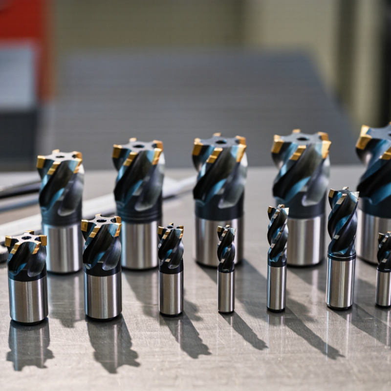
Choosing a chamfering cutter starts with the edge you need to create. A single-flute cutter suits aluminum and softer plastics because it clears chips quickly. Multi-flute designs usually provide smoother finishes in steel and stainless steel. Indexable cutters can reduce downtime during repeated production runs. Countersink cutters are better for screw seating, while 45-degree cutters handle common edge-breaking tasks. Carbide offers wear resistance, but high-speed steel can be practical for lower speeds and occasional work.
Application details matter more than cutter appearance. A thin aerospace panel may need a light, controlled chamfer, not an aggressive pass. A machined steel housing may require several passes to prevent burr rollover. Select the cutter diameter, angle, coating, and flute count together. The 2024 Deloitte Smart Manufacturing and Operations Survey reported that 86% of manufacturers consider smart manufacturing important for future competitiveness. That finding supports using tool-life records, spindle-load data, and inspection results when choosing cutters. Guessing still happens.
Tips: Measure the finished chamfer, not only the programmed depth. Check the workpiece hardness and clamping strength first. Reduce feed if the edge shows tearing or vibration. A perfect-looking edge can hide poor tool wear. In my view, the safest choice is often the cutter that gives stable results, even when its cycle time is slightly slower. Keep a simple log of material, cutter type, speed, feed, and observed burr size. U.S. cutting-tool industry reports also emphasize productivity, repeatability, and tool-life control as major purchasing factors.
Matching Cutter Geometry to Your Material and Machining Goals
Choosing a chamfering cutter starts with the material, not the catalog picture. Aluminum usually responds well to a sharp, positive-rake geometry. It produces cleaner edges and reduces built-up material. Stainless steel needs stronger cutting edges, controlled relief, and stable chip evacuation. Hardened steel often benefits from a smaller chamfer width and rigid, wear-resistant tooling.
Geometry sets the result. A 45-degree included angle suits general edge breaking, while a larger angle can create a wider, more visible chamfer. Fewer flutes often help aluminum clear chips. More flutes may improve finish in steel, but only when feed and rigidity are adequate. According to Grand View Research’s 2024 cutting-tools market report, the sector is projected to grow at over 6% annually through 2030. That growth reflects demand for productivity, but higher speed alone does not guarantee a better edge.
Test the cutter against your real machining goal. For deburring, prioritize predictable width and low burr formation. For countersinking, check diameter accuracy and surface finish. For decorative edges, inspect the toolpath under consistent lighting. I have seen operators blame geometry when the real issue was tool runout or a flexible fixture. The first trial may be wrong. Measure it. A 2023 report from the U.S. Cutting Tool Institute and AMT recorded U.S. cutting-tool consumption at roughly 2.4 billion dollars, showing how much value depends on small process decisions. A practical trial cut remains more reliable than a specification sheet alone.
Choosing the Correct Diameter, Angle, and Cutting Edge Design
How to Choose the Right Chamfering Cutter for Your Needs?
Choosing the correct diameter starts with the hole or edge size. A cutter should reach the target surface without rubbing against nearby walls. For small parts, a compact diameter offers better control and reduces chatter. Larger diameters can cover wider edges, but they demand more machine power. Measure the workpiece carefully. A quick visual estimate is often misleading.
The chamfer angle affects fit, appearance, and assembly clearance. A 45-degree angle suits many general deburring tasks, while steeper or shallower angles may match specific drawings. Always compare the cutter angle with the required chamfer specification. The cutting edge design matters just as much. A single-edge tool can evacuate chips efficiently, especially in softer materials. Multi-edge designs may improve finish and productivity on stable machines. However, more edges are not automatically better. I have seen polished surfaces ruined by excessive feed or poor clamping.
Tips: Match the cutter material to the workpiece hardness. Use a slower feed when entering interrupted edges. Check the first chamfer under magnification. Tiny burrs can reveal excessive runout. Keep the tool rigid, and avoid forcing the cut. Test cuts are worth the extra minute, although I sometimes skip them when production pressure rises. That shortcut often costs more later.
Evaluating Tool Materials, Coatings, and Machine Compatibility
How to Choose the Right Chamfering Cutter for Your Needs?
Tool material directly affects chamfer quality, tool life, and production cost. Carbide cutters suit hardened steels, stainless steel, and continuous CNC work. High-speed steel remains practical for slower machines and occasional maintenance jobs. The 2024 U.S. Cutting Tool Consumption Report, published by industry trade groups, recorded approximately 2.7 billion dollars in annual American tool consumption. That scale reflects a costly reality: small material choices influence large manufacturing budgets.
Coatings need matching, not guessing. A titanium-aluminum nitride coating handles heat during dry or high-speed steel cutting. For aluminum, a polished, low-friction surface often prevents built-up edge. Diamond-based coatings can improve abrasive non-ferrous applications, but their price may not suit short runs. Cutting speed, feed rate, coolant, and workpiece hardness must be checked together. One variable can mislead you.
Machine compatibility is equally important. Confirm spindle speed, holder type, available power, and cutter diameter. A rigid machine may support carbide at higher speeds, while a light benchtop mill may chatter badly. Keep radial runout below 0.01 millimeters when possible; uneven loading quickly damages the cutting edge. I still recheck this measurement after changing holders. It seems excessive. It is not. The wrong cutter can look efficient for ten parts, then fail suddenly. A practical trial on scrap material remains valuable, even after consulting tooling tables and ISO-based cutting recommendations.
How to Choose the Right Chamfering Cutter for Your Needs? – Evaluating Tool Materials, Coatings, and Machine Compatibility
| Cutter Type / Material | Typical Workpiece Materials | Recommended Coating | Strengths | Limitations | Suitable Machine Conditions | Best Use Case |
|---|---|---|---|---|---|---|
| High-Speed Steel (HSS) | Mild steel, low-alloy steel, cast iron, aluminum, brass, and general-purpose plastics | Uncoated or general-purpose nitride coating | Good toughness, lower purchase cost, and better resistance to shock or interrupted cuts than brittle carbide | Lower hot-hardness and wear resistance; generally requires lower cutting speeds | Manual mills, drill presses, lathes, and machines with limited rigidity or spindle speed | Maintenance work, low-volume production, interrupted cuts, and general workshop use |
| Solid Carbide | Hardened or alloy steels, stainless steel, cast iron, aluminum, copper alloys, and engineering plastics | Application-specific PVD or CVD coating; uncoated grades are often used for nonferrous metals | High hardness, excellent wear resistance, and suitability for higher cutting speeds and repeatable production | More sensitive to vibration, impact, overhang, and poor machine rigidity; higher initial cost | Rigid CNC machining centers, CNC lathes, and high-speed spindles with accurate tool holding | High-volume production, consistent chamfer sizes, and automated machining |
| Indexable Carbide Cutter | Steel, stainless steel, cast iron, and selected nonferrous alloys | Grade-specific carbide coating selected for the workpiece and cutting conditions | Replaceable inserts reduce setup time and operating cost; suitable for larger chamfers and heavier material removal | Larger cutter body, possible insert marks, and less flexibility for very small or highly detailed chamfers | Rigid CNC mills, machining centers, and production equipment with adequate spindle power | Large components, repetitive production, and applications requiring quick edge replacement |
| Polycrystalline Diamond (PCD) | Aluminum alloys, copper alloys, graphite, carbon-fiber-reinforced plastics, wood composites, and abrasive nonferrous materials | PCD cutting edge; additional coatings depend on the tool construction and application | Very high wear resistance and long edge life in abrasive nonferrous materials; can produce clean edges | Not generally suitable for ferrous steel because of chemical wear at elevated cutting temperatures; high cost | Highly rigid, low-vibration CNC equipment with precise runout control | High-volume machining of abrasive aluminum, composites, and other nonferrous materials |
| Ceramic or Cermet | Certain cast irons, hardened steels, and finishing applications on stable machines | Usually grade-specific; coating selection depends on the substrate and thermal conditions | High-temperature hardness and potential for high-speed finishing on suitable materials | Brittle compared with HSS and carbide; poor choice for impact, chatter, interrupted cuts, or weak setups | Very rigid CNC equipment, stable workholding, and controlled cutting conditions | Specialized high-speed finishing where vibration and impact are minimal |
Coating Selection Guide
| Coating Family | General Characteristics | Commonly Considered For | Important Selection Note |
|---|---|---|---|
| TiN-Type Coating | General-purpose wear protection and improved surface hardness | Low- to medium-speed machining of steels, cast iron, and some nonferrous metals | Useful for general service, but newer multilayer coatings may provide better performance in demanding applications |
| Aluminum-Titanium Nitride Family | High oxidation resistance and hot hardness compared with basic coatings | Alloy steels, stainless steels, hardened materials, and dry or reduced-coolant machining | Select the exact grade according to cutting temperature, workpiece hardness, and coolant practice |
| Diamond-Based Coating | Very high abrasion resistance and low friction for selected nonferrous applications | Graphite, abrasive composites, aluminum-silicon alloys, and engineering plastics | Generally avoid ferrous materials at elevated temperatures unless the tool supplier specifically approves the application |
| Uncoated Cutting Edge | Sharp edge geometry and no coating-related edge-radius change | Aluminum, copper, brass, plastics, and applications requiring a very sharp edge | Use suitable flute geometry and chip evacuation; coating is not automatically better for every material |
Machine Compatibility and Operating Checks
| Evaluation Dimension | What to Verify | Why It Matters | Practical Selection Guidance |
|---|---|---|---|
| Spindle Speed Range | Confirm that the machine can reach the cutter’s recommended speed range without exceeding the tool’s maximum rated speed | Too little speed can reduce productivity, while excessive speed can cause overheating, rapid wear, or tool failure | Use the tool manufacturer’s cutting-data chart and calculate speed from cutter diameter and recommended cutting speed |
| Machine Rigidity | Assess spindle bearings, table stiffness, workholding, tool overhang, and machine condition | Vibration can damage brittle cutting edges and produce an uneven chamfer | Choose tougher HSS or tougher carbide grades for less rigid setups; reserve ceramic or PCD for stable systems |
| Tool Holder and Runout | Check shank diameter, holder type, balance, cleanliness, and radial runout | Runout causes unequal tooth loading, poor surface finish, and premature edge wear | Use the most accurate compatible holder and keep the cutter overhang as short as practical |
| Coolant and Chip Evacuation | Verify flood coolant, mist, air blast, or dry-machining capability and ensure chips can leave the cutting zone | Recutting chips and poor heat control may damage the chamfer, cutter, or workpiece | Use air blast for many aluminum applications and follow the coating or grade supplier’s coolant recommendations |
| Chamfer Size and Angle | Match cutter angle, diameter, cutting length, and depth capacity to the required edge specification | An unsuitable geometry may create excessive cutting force or fail to reach the required chamfer width | Select a cutter that can produce the required angle in one stable pass whenever possible |
| Feed and Depth of Cut | Confirm machine feed capability, programmed depth, radial engagement, and cutter tooth count | Incorrect feed or excessive engagement can cause rubbing, chatter, burrs, or edge chipping | Begin with conservative values, inspect the chamfer, and adjust only within the tool supplier’s stated limits |
Comparing Performance, Cost, and Maintenance Before Buying
How to Choose the Right Chamfering Cutter for Your Needs?
Performance depends on the workpiece, machine rigidity, and desired edge quality. Hardened steel often needs a rigid cutter with wear-resistant cutting edges. Aluminum usually benefits from polished flutes that resist built-up material. A smooth cutter leaves a cleaner, more consistent chamfer. Check cutting speed, feed rate, and tool overhang carefully. I inspect the first ten parts with a caliper and bright task lighting. Small burrs may indicate incorrect geometry rather than poor operator control. Short setup matters. Maximum speed is not always best. During one shop trial, reducing feed slightly lowered vibration and improved the surface. It also added several seconds per part.
Cost should include tool life, setup time, rejected parts, and replacement frequency. A low purchase price can become expensive when edges wear quickly. Calculate cost per finished component, not cost per cutter. Maintenance includes removing chips, checking runout, and inspecting corner wear. A dull edge creates heat and may damage the workpiece. Keep cutters dry and protected between jobs. Use the correct holder and verify secure clamping before cutting. Record tool usage when production is repetitive. I have replaced cutters too early before. A magnifier showed only light wear. That mistake taught me to inspect evidence first. Still, waiting too long is risky. Select the cutter that balances stable performance, acceptable cost, and manageable maintenance for your actual workload.
How to Choose the Right Chamfering Cutter?
Performance, cost efficiency, and maintenance simplicity are compared using representative, non-brand-specific machining ranges. A higher score is better in every category.
Reference ranges used for the comparison: HSS cutters typically operate at 25–45 m/min with 0.5–1.0 hours of tool life; solid carbide cutters at 80–150 m/min with 1.5–3.0 hours; indexable carbide cutters at 100–180 m/min with 2.0–4.0 hours; and PCD cutters at 200–400 m/min with 10–20 hours. Actual results vary with workpiece material, cutting depth, feed rate, coolant, and machine rigidity.
