
7 Tips for Choosing the Right PSC Tool Holder?
Choosing the right Psc Tool Holder affects accuracy, tool life, setup time, and operator confidence. It is not a minor purchasing decision. A holder may look precise on a catalog page, yet behave differently beside a noisy spindle or during a deep pocket cut.
ISO 26623 defines the PSC interface through a polygonal shank and flange contact. These features support repeatable positioning and strong torque transmission when the machine, holder, and tooling are properly matched. Real results still depend on balance, runout, clamping force, coolant delivery, and maintenance. Small errors matter. A few microns at the holder can become visible marks on a finished aerospace or automotive component.
Industry data reinforces the need for careful selection. The International Federation of Robotics’ World Robotics 2024 report recorded 541,302 industrial robot installations worldwide in 2023. More automated machining cells require stable, repeatable tool changes. Meanwhile, the Association for Manufacturing Technology’s U.S. Manufacturing Technology Orders reports track continuing investment in advanced equipment and production capacity. That investment can be weakened by an unsuitable interface.
The seven tips ahead focus on practical decisions: machine compatibility, taper geometry, runout, balance grade, rigidity, coolant access, and supplier support. Check the drawings. Measure the actual setup. One caution: no holder wins everywhere. A rigid PSC tool holder may improve heavy roughing, but a lighter design could suit high-speed finishing better. I have seen specifications look excellent while shop-floor handling felt awkward. That gap deserves honest review. Selection should combine standards, test data, operator experience, and the manufacturer’s technical evidence.
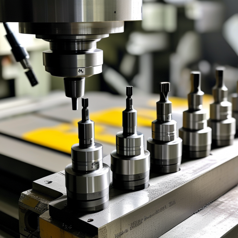
Define the PSC Tool Holder and Its Role in Machining
A PSC tool holder uses a polygonal shank and flange contact to locate cutting tools accurately. ISO 26623-1 defines this connection system for high-precision machine-tool interfaces. Its role is practical: it transfers cutting forces, controls radial runout, and supports stable tool changes. The holder also affects surface finish, tool life, and spindle workload.
The 2024 World Machine Tool Survey reported global machine-tool consumption above 80 billion dollars in 2023. That scale makes small interface errors expensive.
Choose carefully. Check the machine’s PSC size and spindle specification. Confirm the holder matches the required cutter diameter. Measure runout at the gauge line, not only at the taper. Review balancing data for the intended spindle speed.
Inspect flange contact for chips, dents, or raised metal. Compare coolant delivery with the tool’s internal passages. Finally, verify pull-stud compatibility and clamping force. These seven checks sound simple. They are often skipped.
In daily machining, I clean both contact surfaces before every installation. A thin chip can change tool position. I also record runout after heavy cutting, because vibration may reveal damage earlier than visual inspection.
A holder rated for high speed is not automatically suitable for every cutter. That assumption needs challenging. The safest choice balances accuracy, rigidity, speed, coolant access, and maintenance effort. Data from ISO 26623-1 supports the interface definition, while shop measurements confirm whether the real assembly performs as expected.
Match the Holder Interface to Your Machine and Spindle
7 Tips for Choosing the Right PSC Tool Holder?
Match the Holder Interface to Your Machine and Spindle
Choosing a PSC tool holder starts at the spindle, not the cutting tool. Confirm the exact polygon size, flange geometry, and gauge-line specification in the machine manual. Fit is not a guess. The holder must seat fully against the spindle face, while the drawbar applies the correct retention force. A mismatched interface can create vibration, poor repeatability, and premature wear.
Check the spindle taper and contact surfaces for damage or contamination. Even a small chip can affect axial positioning. Verify coolant delivery, because internal and external channels need different holder designs. Consider the machine’s speed range and select a holder with suitable balance quality. Measure tool runout at the gauge line when accuracy matters. Keep the measurement record. It helps reveal gradual wear.
I have seen operators focus on the cutter while overlooking the spindle connection. That mistake is easy to repeat. Check the drawbar thread, retention knob, and available clearance before ordering. Confirm the holder length against the machine’s travel and work envelope. Shorter is not always better. A rigid holder may improve stability, but access can suffer in deep cavities. Review the actual machining setup, not only the catalog drawing. A careful check can still miss something, especially when older equipment has been modified. When uncertain, ask the machine builder or a qualified tooling engineer to verify the interface dimensions.
Choose the Right Size, Reach, and Rigidity for the Operation
7 Tips for Choosing the Right PSC Tool Holder
Choose the Right Size, Reach, and Rigidity for the Operation
Choosing a PSC tool holder starts with the operation, not the catalog photograph. Match the holder size to the spindle interface and machine capacity. A holder that is too small may flex under heavy cutting loads. One that is too large can waste clearance and add unnecessary mass.
Keep the reach as short as practical. Measure from the spindle face to the cutting edge, then check fixture and workpiece interference. Long reach increases deflection, especially during deep pocketing or hard turning. It may look convenient. It often is not. Select the shortest holder that still provides safe access. Consider the cutting tool diameter, insert geometry, and required working angle before deciding.
Rigidity deserves close attention. A thick body, secure clamping, and accurate seating help control vibration and runout. Inspect the polygon contact surfaces for damage or contamination. Even a small chip can affect repeatability. I have seen operators blame cutting data when the real problem was a poorly cleaned interface. That mistake is easy to repeat. Do not assume a higher load rating guarantees better results; the complete tool assembly still matters. Check balance requirements, coolant delivery, pull stud condition, and compatibility with the machine’s automatic tool change system. Test the holder at a moderate load, record vibration and surface finish, then adjust reach or cutting parameters when evidence demands it.
| Tip | Selection Dimension | Recommended Practice | Typical Starting Data | Why It Matters | Verification Checklist |
|---|---|---|---|---|---|
| 1 | Match the PSC Interface Size | Select the PSC shank size specified by the machine spindle, automatic tool changer, and approved coupling standard. Do not select a holder only by tool diameter. | Use the machine’s certified PSC size and gauge-line specification; the holder, spindle, pull-in mechanism, and tool changer must use the same interface. | An incorrect interface can prevent accurate seating, reduce repeatability, and create a serious tool-security risk. | Confirm shank size, gauge length, flange details, pull stud or retention method, coolant passage, and machine-tool documentation. |
| 2 | Choose the Shortest Practical Reach | Use the shortest holder and tool projection that provides clearance from the workpiece, fixture, and machine enclosure. | For milling, begin near a tool overhang of 3–4 × tool diameter where access allows. For drilling, keep the holder projection as short as the hole depth and coolant requirements permit. | Tool deflection and vibration increase rapidly as overhang increases. A shorter setup normally improves surface finish and dimensional control. | Measure total projection from the holder face to the cutting edge, including the collet, extension, shrink-fit section, and cutting tool. |
| 3 | Prioritize Rigidity for Heavy Cutting | Use a high-rigidity PSC holder with a solid or short tool connection for roughing, hard materials, interrupted cuts, and high radial loads. | For heavy milling, target an effective overhang below approximately 4 × tool diameter whenever possible. Use a larger, stiffer connection when machine clearance permits. | Higher bending stiffness helps control chatter, tool deflection, insert damage, and uneven cutting forces. | Check holder wall thickness, tool clamping length, contact condition, balance grade, and the machine’s allowable spindle load. |
| 4 | Select the Clamping Method by Operation | Choose hydraulic, shrink-fit, high-precision collet, or milling chuck technology according to the required accuracy, torque transmission, and tool diameter. | Precision finishing commonly benefits from low-runout clamping, typically around 3–5 μm at the specified gauge length. Heavy roughing requires strong torque transmission and secure axial location. | Clamping method affects runout, tool life, balance, torque capacity, and the ability to withstand impact loads. | Review stated runout measurement conditions, maximum speed, allowable tool shank tolerance, clamping length, and maintenance requirements. |
| 5 | Size the Holder to the Cutting Tool | Use a holder with a compatible tool shank diameter and sufficient clamping length. Avoid reducing sleeves or excessive clearance when maximum rigidity is required. | Typical solid-tool shank ranges include 6, 8, 10, 12, 16, 20, and 25 mm. Use at least the tool maker’s specified minimum clamping length; longer engagement is preferred when it does not interfere with flutes or coolant ports. | A properly matched shank and clamping length improve torque transfer and reduce tool pullout or fretting. | Confirm shank diameter tolerance, minimum insertion depth, relieved-shank restrictions, cutting-tool balance, and interference with the holder nose. |
| 6 | Consider Speed, Balance, and Coolant Delivery | For high-speed machining, select a dynamically balanced holder and verify that coolant delivery matches the tool and cutting conditions. | For rotational speeds above approximately 10,000 rpm, verify the holder’s declared balance and maximum speed. Through-tool coolant is useful for deep holes, difficult-to-cut materials, and chip evacuation. | Imbalance produces centrifugal forces that increase with the square of speed, while poor coolant delivery can cause heat buildup and chip recutting. | Check maximum rated rpm, balance condition, coolant pressure and flow, sealing method, and whether the tool has internal coolant channels. |
| 7 | Account for Accuracy, Repeatability, and Maintenance | Choose the holder based on the required feature tolerance, tool-change frequency, and inspection plan. Keep all mating surfaces clean and undamaged. | For finishing, verify radial runout at the actual gauge length and use a repeatable presetting method. Inspect the PSC contact surfaces before every setup and clean them with a lint-free method. | Contamination or damaged contact surfaces can shift the tool centerline, alter tool length, and reduce repeatability between tool changes. | Record runout, tool length, gauge-line condition, clamping torque or procedure, inspection frequency, and replacement criteria for worn components. |
Note: The values shown are practical starting points for tool-holder selection. Final holder size, speed, reach, clamping method, and cutting parameters must be confirmed against the machine, tool, workpiece material, fixture clearance, and holder manufacturer’s technical specifications.
Evaluate Clamping Accuracy, Balance, and Tool Compatibility
Choosing the Right PSC Tool Holder: Evaluate Clamping Accuracy, Balance, and Tool Compatibility
A reliable PSC tool holder starts with accurate clamping. Inspect the taper and flange for clean, even contact. Measure runout near the tool nose, not only at the holder. A small error there can become a visible cutting mark. Check the clamping force with approved measuring equipment. Do not trust hand feel alone. I once overlooked a slightly damaged contact surface, and the first test cut revealed the mistake. That experience changed my inspection routine.
Balance matters when spindle speed rises. Ask for balance data that matches your actual operating speed. A holder balanced for one range may perform poorly in another. Check the weight distribution around the centerline. Then inspect the pull stud, retention system, and machine interface for compatibility. These parts must work together, not merely fit separately. Confirm the holder supports your cutter diameter, coolant method, and required reach. Excessive projection can reduce stiffness and increase vibration.
Test the complete setup before production. Use a clean tool, a measured gauge length, and a controlled trial cut. Listen for irregular sound, watch the surface finish, and record temperature changes. Recheck runout after repeated tool changes. It may shift slightly. That detail is easy to dismiss, but it can expose wear or contamination. Review maintenance instructions and replacement limits from reliable technical documents. A careful comparison of accuracy, balance, and compatibility usually reveals weaknesses before they become costly.
7 Tips for Choosing the Right PSC Tool Holder
Evaluate clamping accuracy, balance, and tool compatibility before selecting a PSC tool holder.
The chart presents a practical 100-point evaluation model: clamping accuracy receives the highest priority because low runout improves tool life and machining consistency. Balance is especially important at high spindle speeds; ISO 1940-1 balance grades such as G2.5 are commonly used for precision rotating assemblies. Compatibility includes the PSC interface, tool diameter range, retention method, coolant delivery, and machine spindle requirements. Always verify the holder's certified runout, permissible speed, balance condition, and dimensional fit against the machine and cutting tool specifications.
Compare Quality, Maintenance Needs, and Total Operating Cost
7 Tips for Choosing the Right PSC Tool Holder
Compare Quality, Maintenance Needs, and Total Operating Cost
A PSC tool holder should be judged beyond its purchase price. In practical shop-floor evaluations, runout, taper contact, and balance reveal quality quickly. Check measured runout at the cutting end, not only the catalog specification. A holder that stays within tight limits supports better surface finish and tool life. Inspect the clamping mechanism, pull stud interface, and coolant passages. Small defects become expensive vibration.
Maintenance needs deserve equal attention. Ask how often the holder requires cleaning, inspection, and component replacement. A practical design allows operators to reach contact surfaces without special procedures. Wipe the taper before every setup; one fine chip can shift tool position. Store holders vertically, capped, and away from grinding dust. Keep inspection records. They expose repeated failures, although our records were imperfect at first. We sometimes blamed the machine too soon.
Compare total operating cost over a year, not just invoice price. Include replacement collets, cleaning time, downtime, rejected parts, and calibration labor. Calculate cost per production hour. A cheaper holder may lose its advantage after frequent retightening. Test two samples under the same speed, load, and coolant conditions. Measure runout, temperature, tool changes, and part quality. Ask the supplier for material data, tolerance reports, and service guidance. Independent verification matters. Choose the holder that performs consistently, remains maintainable, and gives technicians clear evidence.
