
Request A Quote

Phone: 416-244-6476
Email:

    Why Choose a Copper Stamping Machine?

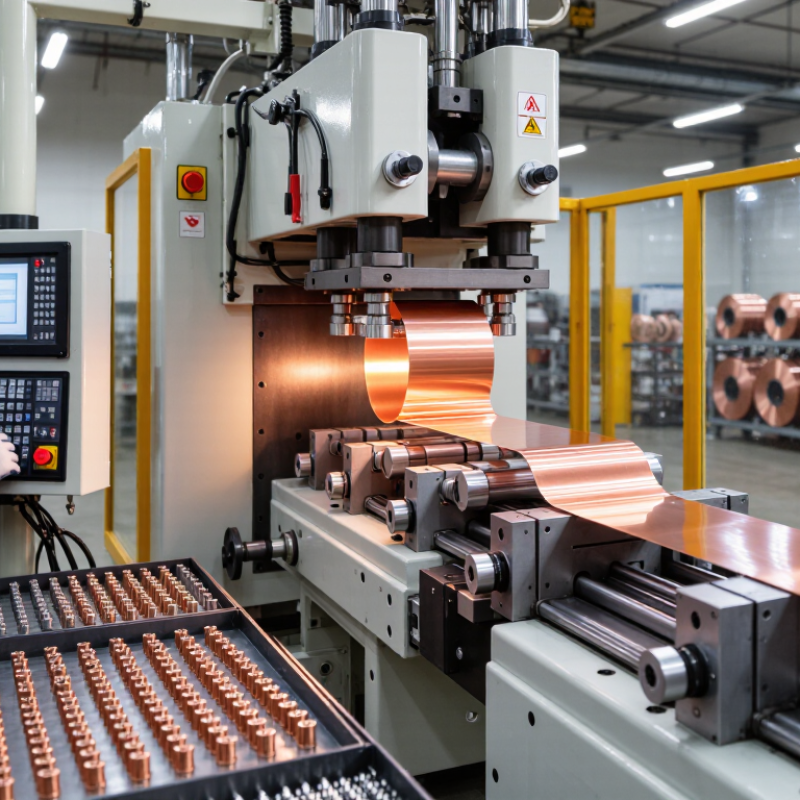
    Choosing a Copper Stamping Machine can improve production consistency, especially when copper parts require clean edges, accurate shapes, and repeatable dimensions. Copper conducts heat and electricity efficiently, but it also deforms easily under pressure. The right machine must handle this balance with controlled force, stable tooling, and reliable feeding.

    In practical workshops, operators often inspect the strip, adjust the die clearance, and test several samples before full production. These small steps reduce burrs, surface marks, and material waste. A well-designed machine can support terminals, connectors, busbars, washers, and other electrical components. It may also shorten cycle times when paired with suitable dies and automatic feeding equipment. Speed alone is not enough. Poor alignment can damage expensive copper stock.

    Experienced manufacturers evaluate tonnage, stroke length, working speed, coil width, and maintenance access before selecting equipment. They also review safety guards, emergency stops, noise levels, and supplier support. Technical data matters. Real production trials matter more. A machine that performs well in a demonstration may need different settings in your facility.

    There is no universal answer.

    The best choice depends on material thickness, part geometry, output targets, and quality standards. Buyers should request sample testing and examine long-term operating costs, not only the purchase price. Energy use, die replacement, operator training, and downtime can change the final calculation. Even careful planning has limits. Copper quality can vary, and early assumptions may need revision. A thoughtful comparison makes the investment more dependable and easier to justify.
    Why Choose a Copper Stamping Machine?

    Copper’s 58 MS/m Conductivity and 100% IACS Electrical Performance

    Why Choose a Copper Stamping Machine?

    Copper’s 58 MS/m Conductivity and 100% IACS Electrical Performance

    Copper stamping supports accurate, repeatable production of terminals, busbars, clips, and conductive shields. The International Annealed Copper Standard defines 100% IACS as 58 MS/m at 20°C. This benchmark explains copper’s low electrical resistance and strong current-carrying performance. It also gives engineers a clear comparison point during material inspection.

    The number is impressive, but it is not a guarantee. Surface oxidation, burrs, die wear, and poor contact pressure can reduce real-world performance. Precision stamping helps maintain stable dimensions across thousands of parts. Proper die clearance also limits edge damage and unnecessary material loss. The U.S. Geological Survey estimated global copper mine production at about 22 million metric tons in 2024. Meanwhile, the International Copper Study Group continues to report strong demand from electrical equipment and energy infrastructure. Efficient forming matters more as copper use expands.

    Tips:

    Check conductivity certificates at 20°C. Match punch clearance to the copper grade and thickness. Inspect burr height under magnification. Use clean tooling and controlled lubrication. Remember that stamped copper may harden during forming, affecting springback and fit. A practical trial run is still essential. Theory can miss small production problems.

    How Stamping Presses Reach 1,200 Strokes per Minute in Production

    Why Choose a Copper Stamping Machine?

    How Stamping Presses Reach 1,200 Strokes per Minute in Production

    Reaching 1,200 strokes per minute requires more than a powerful motor. It depends on a short, controlled stroke and a die designed for rapid movement. High-speed presses coordinate the crankshaft, feeder, and strip sensor within milliseconds. The feeder advances copper strip only after the die opens. This prevents material drift and reduces collision risks.

    Copper is soft, conductive, and highly responsive to heat. At extreme speeds, poor lubrication can create burrs, scratches, or inconsistent edges. A stable press frame limits vibration, while precision guides keep the upper and lower die aligned. Operators also monitor strip tension, feed length, and die temperature during production. Small progressive parts may reach 1,200 strokes per minute. Larger connectors usually require a slower setting.

    Speed alone is not the target. Quality matters more. A practical setup may begin near 700 strokes per minute, then increase gradually after checking samples. Inspectors measure hole position, flatness, and burr height under magnification. Automatic sensors can stop the line when a strip misfeeds or a part remains in the die. That safeguard saves tooling, although sensors can still miss subtle defects. Regular cleaning is essential. Copper particles build quickly around the die area. A careful maintenance record helps technicians identify patterns before defects become expensive.

    Why Choose a Copper Stamping Machine? - How Stamping Presses Reach 1,200 Strokes per Minute in Production

    Production Dimension Typical Data Example at 1,200 Strokes per Minute Production Significance
    Recommended Copper Applications Electrical terminals, contact clips, busbar components, connector parts, shielding pieces, and spring contacts Continuous coil-fed production using a progressive die Copper’s high electrical conductivity makes it suitable for parts requiring efficient current transfer.
    Typical Copper Strip Thickness Approximately 0.10–2.00 mm, depending on alloy, part geometry, and press capacity A high-speed terminal line commonly processes thin strip, often below 1.00 mm Thinner strip and simpler geometries generally permit higher operating speeds.
    Operating Speed Range High-speed copper stamping: approximately 300–1,200 strokes per minute 1,200 strokes per minute = 20 strokes per second The maximum rate depends on die design, stroke length, material thickness, feed stability, and part complexity.
    Stroke Length Common high-speed applications use approximately 10–30 mm strokes A short 20 mm stroke reduces unnecessary movement at high speed Shorter strokes help reduce cycle time, vibration, and mechanical loading.
    Theoretical Output per Hour Output = strokes per minute × parts per stroke × 60 1,200 × 1 × 60 = 72,000 parts per hour This is a theoretical figure before downtime, scrap, coil changes, inspection, and tooling adjustments.
    Multi-Part Die Output Progressive dies may produce two or more parts per stroke 1,200 × 2 × 60 = 144,000 parts per hour for a two-up layout Multi-up tooling increases output without increasing press speed, provided strip layout and die balance are suitable.
    Practical Production Utilization Approximately 70–85% of theoretical capacity in a stable production environment 72,000 theoretical parts/hour × 80% = about 57,600 good parts/hour Actual output reflects setup time, maintenance, material replenishment, inspection, stoppages, and scrap.
    Press Capacity High-speed applications commonly use compact presses from approximately 15–80 metric tons The required tonnage must be calculated from shear length, material strength, thickness, and die configuration Selecting excess capacity can reduce efficiency, while insufficient capacity may damage the press or tooling.
    Feed Accuracy Approximately ±0.02–0.05 mm in well-controlled high-speed applications Accurate servo or mechanical feeding keeps each strip advance aligned with the die stations Consistent feed accuracy improves dimensional repeatability and reduces die crashes.
    Key Features for 1,200 SPM Operation Rigid frame, balanced slide, low-inertia drive, precise feeder, lubrication, die monitoring, and vibration control All systems must remain synchronized at 20 cycles per second High-speed performance is achieved through coordinated press, feeder, tooling, lubrication, and quality-control systems.
    Material Efficiency Progressive strip layouts can achieve approximately 60–90% material utilization, depending on part shape and carrier design An optimized layout reduces copper scrap while maintaining sufficient carrier strength Because copper is a relatively high-value material, strip nesting and scrap recovery have a direct effect on production cost.
    Note: All values are typical engineering ranges for high-speed copper stamping and should be verified against the specific copper alloy, strip thickness, part geometry, die design, press tonnage, and required quality level.

    Why Progressive Dies Can Achieve ±0.01 mm Part Tolerances

    Why Choose a Copper Stamping Machine?

    Progressive dies can achieve ±0.01 mm part tolerances when the process is carefully controlled. Copper responds well to high-speed stamping because it is conductive, formable, and available in consistent sheet gauges. A copper stamping machine feeds the strip through several stations in one cycle. Each station performs a controlled operation, such as piercing, bending, or cutoff.

    The die structure does much of the precision work. Guide posts and bushings keep upper and lower sections aligned during every stroke. Accurate strip feeding prevents pitch errors between stations. Controlled clearance reduces burrs and limits material distortion. Press rigidity also matters. Even slight frame movement can affect a narrow terminal or contact spring. Stable speed, suitable lubrication, and sharp punches support repeatable results.

    However, ±0.01 mm is not automatic. Copper temper, sheet thickness, heat, and tool wear can change the final dimension. Small burrs matter. A reliable process uses first-piece checks, in-process measurements, and scheduled die maintenance. Optical inspection or coordinate measurement can verify critical features, but numbers need context. The tolerance may apply to one dimension, not the entire part. Production teams should also review actual capability data before promising this level. That extra review can feel slow, yet it often prevents costly batches of inaccurate components.

    Material Efficiency: Reaching 70–90% Utilization with Strip Stamping

    Why Choose a Copper Stamping Machine?

    Material efficiency is a practical reason to choose a copper stamping machine. With strip stamping, carefully planned nesting can achieve 70–90% material utilization. The remaining 10–30% becomes edge trim, carrier material, or scrap. In a production trial, a 0.8 mm copper strip may produce hundreds of terminals per coil, with only narrow bridges between parts. Small changes matter.

    The U.S. Geological Survey’s Mineral Commodity Summaries 2024 estimated global mined copper production at about 22 million metric tons in 2023. This scale makes material conservation commercially important, not merely environmental. Progressive stamping reduces repeated setup waste and maintains consistent pitch between components. Automatic feeding also limits manual errors. Less handling helps.

    Still, 90% utilization is not guaranteed. Part geometry, grain direction, burr control, and required electrical clearances can reduce the result. That is where engineering judgment matters. A tool designer should test several strip layouts before approving production. The International Copper Study Group continues to track strong global copper demand from electrification and infrastructure. Higher demand can increase material costs and pressure manufacturers to measure every kilogram. One overlooked carrier bridge may seem insignificant, but thousands of coils can expose the mistake.

    Selecting Tonnage, Feed Rate, and Die Design for Copper Alloys

    Why Choose a Copper Stamping Machine?

    Copper stamping starts with the material, not the machine. The USGS Mineral Commodity Summaries 2024 reported about 22 million metric tons of mined copper in 2023. That scale reflects copper’s industrial importance, but each alloy still behaves differently under pressure.

    Choose tonnage from the actual cutting perimeter, sheet thickness, and alloy strength. A practical estimate uses perimeter × thickness × shear strength, then adds a 20–30% safety margin. C110 copper cuts differently from tougher brass or phosphor bronze. Too little capacity causes incomplete cuts and unstable production. Too much capacity may increase energy use and tool stress. The margin is useful, but perhaps conservative for every job.

    Feed rate should match pitch, stroke rate, and strip stability. A simple calculation is pitch multiplied by strokes per minute. Start slower when burrs appear or narrow bridges deform. Die clearance deserves equal attention. ASM Handbook guidance shows that clearance must reflect material thickness and ductility. For many copper sheets, technicians begin near 5–8% of thickness per side, then adjust through trial cuts. Burr height, edge rollover, and slug pull-through provide better evidence than theory alone. The Copper Development Association identifies annealed pure copper as approximately 100% IACS conductivity, while alloy additions can reduce conductivity and change forming behavior. Small details matter. A polished guide, sharp punch, and controlled lubrication often prevent costly misalignment. Industry figures provide direction, not certainty. Actual die trials remain essential.

    Why Choose a Copper Stamping Machine?

    Selecting Tonnage, Feed Rate, and Die Design for Copper Alloys

    Typical tensile strength increases the forming-load requirement, while electrical conductivity helps identify the functional role of each copper alloy. Press tonnage should be calculated from the blanking perimeter, material thickness, shear strength, and a safety allowance. Feed rate should match the strip pitch and press stroke rate, while die clearance must be adjusted for alloy strength, thickness, and the required edge quality.

    Representative values for commonly used copper alloys in annealed or typical commercial conditions. Actual properties vary with temper, thickness, and applicable material standard.